Table of Contents
Network
A model may include one network, that is a directed graph with attributes on its nodes and edges. The network is a more complex model allowing relative production priorities, buffers and the creation of network topologies that cannot be modelled using the simple series/parallel topology and logic imposed by an availability diagram.
In a network model, the top diagram has a single group, that is the network group. Inside the network group is the network diagram, it can be either serial or parallel but it must have no nested structure or may comprise a single group only. That is because a network diagram is interpreted as a node list. The groups and items of the network diagram are the nodes of the network, in the same order. They are numbered consecutively, starting with 1. The network can have arbitrary topology, as explicitly set through the network editing interface.
The Z network sets an example, it is the smallest network that is not a reliability block diagram.
It has:
* 2 production nodes c0, d0
* 2 consumption nodes c1, d1
* 3 edges (c0, c1), (d0, d1), (d0, c1)
* 1 hidden source node and 1 hidden sink node
Network editing
The network-edit toggle (Ctrl+Z) provides access to the network form. With that, you can:
- edit node attributes
- add and delete edges
- add and delete buffers
- edit buffer attributes
For example:
* in the diagram, select d0
* in the network form:
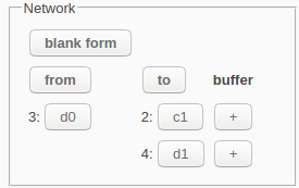
  * hit the 'wipe form' button
  * hit the 'from' button
You then see:
* the list of edges from d0
* for each node, a 'node-edit' button
* for each edge, a 'buffer-add' button
By default, the nodes that have no incoming or no outgoing edges get a hidden edge from the source or to the sink, respectively. Singleton nodes get both. The network must have at least one edge from the source and one edge to the sink.
With a blank network form, pushing the 'from' and 'to' buttons will show the nodes that have an edge from or to all the selected nodes, respectively. In other words, the nodes shown span a Kuratowski subgraph.
With a non-blank network form, pushing the 'from' or 'to' buttons will add, modulo 2, all edges from or to the selected nodes to or from the nodes in the 'to' or 'from' column. Adding the same edge twice will delete it. In this case, the “from' and 'to' buttons toggle.
The node buttons and add-buffer buttons provide access to the node and buffer forms. These forms are for editing the attributes of the nodes and the buffers.
Network diagram editing
Some diagram edit operations have additional functionality and some restrictions to facilitate network construction.
When used on a network diagram, the group operation requires that the selected nodes form a sub-graph that corresponds to a single series or parallel diagram, without nesting. In that case, it puts the selected nodes in a new group, with the corresponding diagram. It ignores the edge directions and the buffers, if any.
The ungroup operation also requires that the selected group has no nested structure. In that case, it replaces the selected group by the sub-graph that corresponds to the group diagram. This includes the nodes and the edges.
The duplicate, replicate and paste operations require that the resulting network diagram has no nested structure. In that case, they add the copied nodes to the network, without their attributes and edges.

